In part one of this series, I looked at wireless access points from Meraki and Ruckus. I also looked at a controller from Ruckus and an old Linksys wireless card. In part two, I am going to look at AP’s from Aerohive, Aruba, and Cisco. This post has a lot more photos in it! As always, you can click on the photo to get a full size image.
Aerohive 120 Access Point
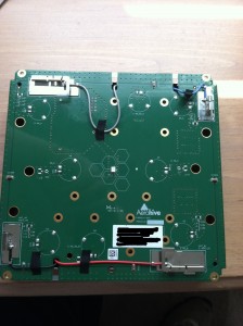
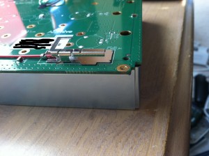
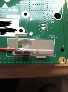
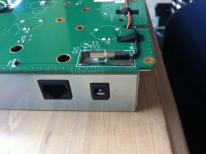
I didn’t take a bunch of photos of this particular AP because it is their lower end model. What I did want to show was the antenna position. It is a dual radio AP capable of running 2.4GHz and 5GHz simultaneously.
The larger antennas connected with the red and gray wires are for the 2.4GHz radios. The smaller antennas connected with the black and blue wires are for the 5GHz wires.
Aerohive 330 Access Point
Here’s what the 330 looks like before I opened it up. This is a 3×3:3 indoor AP.
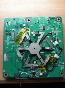
You take off the cover and you see the antenna array. Look familiar? It is the same pattern as the Meraki MR24.
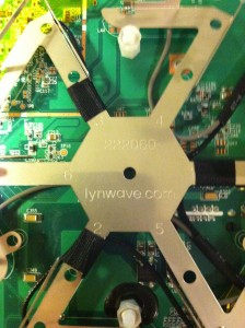
Here’s a closer shot of the antenna array with the manufacturer listed.
Here’s a shot of the TPM chip.
When you see me holding the AP in pictures, it is because the other side of the circuit board is holding the antennas and I can’t set it down without bending those delicate metal pieces.
Flip the AP over and you can see the radios on the bottom right and the CPU on the bottom left.. They are covered, but we’ll take care of that in a second. 🙂
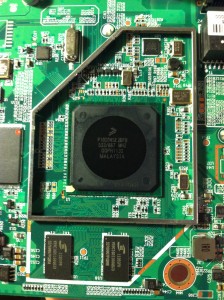
Here is the processor.
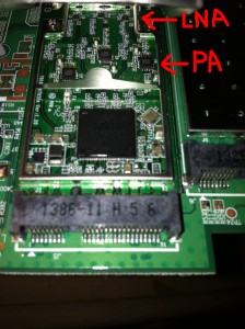
Here is one of the radios. It has an Atheros chipset(which is at the bottom of the photo), but this particular AP has separate PA’s and LNA’s. Since it is a 3×3:3, there are 3 of each component.
Here’s a close up of the radios. The 5GHz is on the left and the 2.4GHz is on the right.
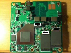
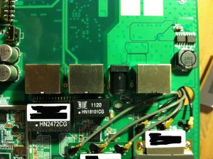
A zoomed out view of the radios. You can see the Ethernet, console, and power ports in the middle.
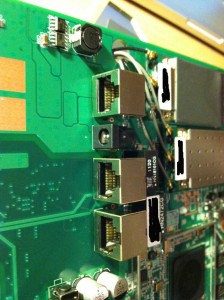
Here’s a better view of the ports.
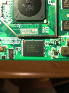
As best I can tell, this is flash memory.
And this appears to be DRAM.
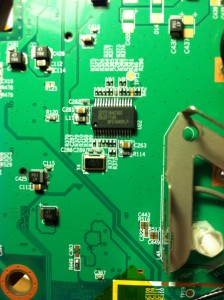
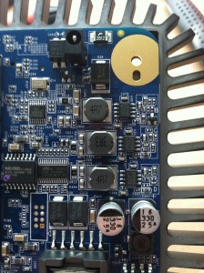
Finally, a few shots of random components.
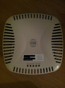
Aruba Instant IAP-135
This is a 3×3:3 AP that can function as a virtual controller and manage up to 16 AP’s. It can also be converted to function as a normal lightweight AP.
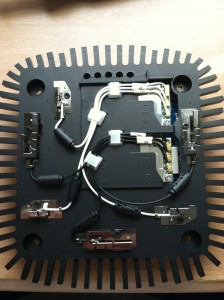
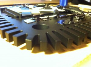
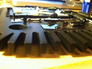
One thing you notice right away is that this AP is not light. When you take the plastic covering off you see why. It reminds me of a giant heatsink.
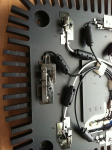
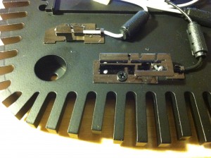
Here’s some closer shots of the antennas. Remember that the smaller antennas are for 5GHz and the larger ones are for 2.4GHz.
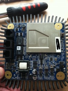
Here’s what the other side of the AP looks like:
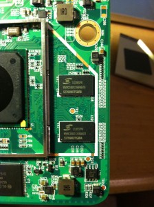
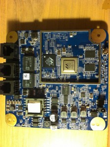
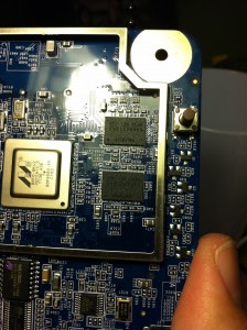
Let’s pull off that metal cover and see what is underneath! It looks like we found the processor. It is a Marvell 88F6560 according to the numbers on the chip. The processor is the silver looking chip in the middle. To the left of it is another Marvell chip. My guess is that it is a Gigabit Ethernet transceiver. Similar model numbers are found in the Marvell Alaska line here.
The 2 small black chips appear to be Samsung SDRAM. Not sure how much in each one though.
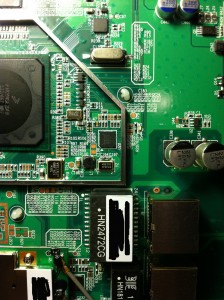
Here are some more chips on the same side, just outside the metal enclosure area. The MXIC chip is some sort of flash memory chip. Not sure what the Atmel chip is next to it.
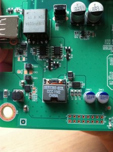
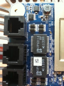
One last pic for this side of the AP. Here is a close up of the chips next to the Ethernet and console interfaces.
Flip the AP over and you can see where the radios themselves are.
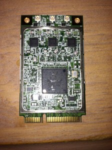
Unscrew the containing bracket and you can then pop out the individual radios. Here’s what they look like by themselves. This is the Atheros AR9390 chip.
With both radios removed, not much is left underneath.
There is a single chip from Texas Instruments, but I am not sure what it does. Searching by part number was inconclusive.
The Aruba 135 was by far my favorite AP to take apart! Lots of interesting things. I especially liked the pop out radios.
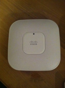
Cisco 1142 Access Point
If there was one word I would use to describe this AP, it would be “sturdy”. It was a little heavy, but that’s because the back side of the AP is metal. The front side surrounding the center piece with the LED and Cisco logo is plastic, but not cheap plastic. It felt like a quality piece of hardware and I didn’t feel like I was going to break it while disassembling it. I can’t say the same for some of the other AP’s.
Let’s open her up and see what is inside!
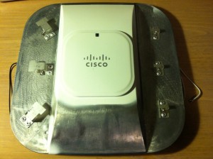
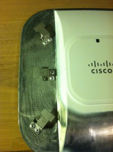
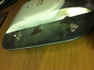
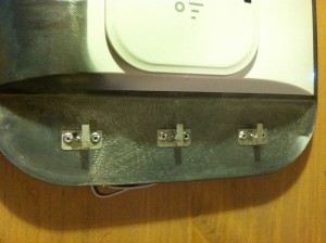
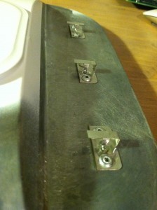
With the top off, you can see the six antennas. The three on the left are the 2.4GHz antennas, and the three on the right are the 5GHz antennas.
Here are some closer shots of the antennas.
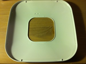
The part covering the antennas is plastic. That would make sense as the rest of the AP is metal. 🙂
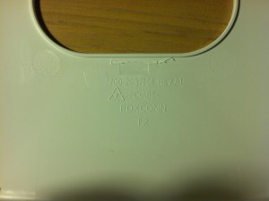
Look closer at who made this plastic component. Does that name ring a bell?
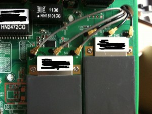
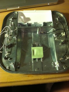
Flip the AP over and you can see the wires connected to the antenna. I disconnected them from the radios in order to take this picture. Otherwise, you wouldn’t be able to see much of the guts of the AP.
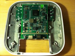
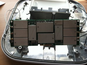
The insides of the AP is basically comprised of two separate boards. One houses the radios and the other has the processor, memory, etc. Here’s a picture of both of them. The board housing the radios is in the back and is wider than the main circuit board.
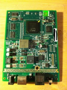
Here’s the main circuit board disconnected from the radio board. You can see the CPU in the middle.
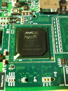
A closer shot of the CPU. You can find the specifications on the CPU here.
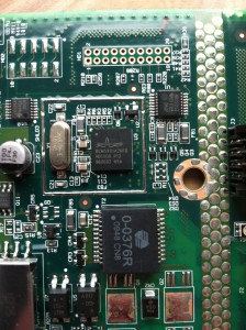
A closeup of the Broadcom gigabit transceiver.
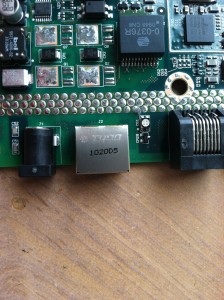
In case you were wondering, Tyco(now TE Connectivity) makes the Ethernet port.
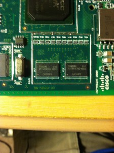
My guess is these 2 Samsung chips are SDRAM or some other sort of memory.
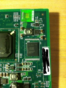
I think this is some type of Intel memory.
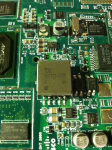
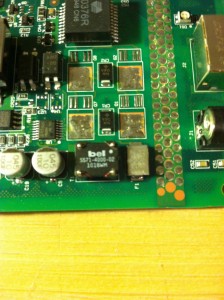
Some additional random circuit board shots.
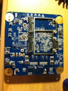
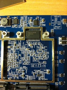
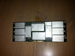
Here is the radio board. Unfortunately, the metal covers over the chips were sealed. I could not pull them off without breaking things and I didn’t want to destroy a working AP. Perhaps when this 1142 is dead, I will tear into it, but for now, it must remain a mystery what is underneath those metal covers.
Here it is with the antennas disconnected.
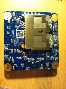
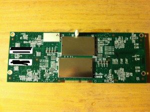
Finally, here is the other side of the radio board.
Closing Thoughts
A lot of what I saw when I took these devices apart was somewhat of a mystery to me. It led me down many rabbit holes on chip distributor websites. Most of these sites had some Chinese language displayed, which should give one an idea of where all the components are being manufactured. Admittedly, I have a LOT to learn about the how and why when it comes to AP hardware. However, being a visual person, simply taking these things apart gave me a better understanding how things work from a layer 1 perspective. I have some additional hardware to take apart and look at, but none of it will be wireless, unless you count the Cisco 871W router I have. The wireless piece in that platform is less than exciting.
Disclaimer: As a delegate for Gestalt IT’s Wireless Field Day 2, I received the Aerohive AP 120, and the Aruba AP 135 for my own personal use. I also happen to be employed by an Aerohive and Cisco partner, so taking apart their gear will only help me in my future engineering endeavors supporting/installing/selling their gear.



One Response to Inside Wireless Hardware – Part 2