I’m going to start out by telling you something you probably already know. Every vendor has their own way of doing things. Sometimes it makes perfect sense, and other times you end up scratching your head wondering why that particular vendor implemented this feature or product. Since I have been spending a lot more time on wireless these days, I came across an issue that forced me to reconsider how transmit power control(TPC) actually works in a Cisco wireless deployment. I thought I would impart some of this information to you, dear reader, in the hopes that it may help you. If you spend a lot of time inside Cisco wireless LAN controllers, this may not be anything new to you.
The Need For TPC
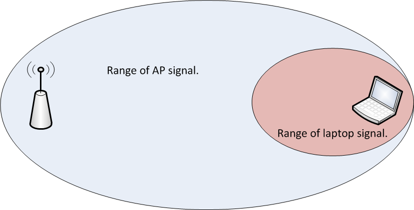
If you have been around wireless long enough, you have probably dealt with wireless installs where all of the access points(AP) were functioning autonomously. While this isn’t a big deal in smaller environments, consider how much design work goes into a network with autonomous access points that number into the hundreds. It isn’t as simple as just deciding on channels and spinning all the access points up. You also have to consider the power levels of the respective access points. Failure to do so can result in the image below where the AP is clearly heard by the client device, but the AP cannot hear the client since it is transmitting at a higher power level than the client can match.
Now consider the use of a wireless LAN controller to manage all of those APs. In addition to things like dynamic channel assignment, you can also have it adjust the transmit power levels of the APs. This can come in handy when you have an AP fail and need the other APs to increase their transmit power to fill the gap that exists since that failed AP is no longer servicing clients. I should point out that proper design of a wireless network with respect to the client transmit power capabilities should NEVER be overlooked. You ALWAYS want to be aware of what power levels your clients can transmit at. It helps to reduce the problem in the image above.
There’s also the problem that can arise when too many APs can hear each other. It isn’t just about the clients. Wireless systems which adhere to the IEEE 802.11 standard are a half duplex medium. Only one device can talk at a time on a given channel. Either a client or the AP will talk, but not both at once. If an AP can hear another AP on the same channel at a usable signal, the airtime must be shared between those APs. Depending on the number of SSID’s in use, this can dramatically reduce the amount of airtime available for an AP to service a client. You can see some actual numbers with regard to SSIDs and APs in this blog post by Andrew von Nagy.
As you can see from two quick examples, there is a need to control the power level in which an AP will transmit. On controller based wireless networks(and even on the newer controller-less solutions), this is done automatically. I wouldn’t advise you turn that off unless you really know what you are doing and you have the time to plan it all out beforehand.
The Cisco Approach
On wireless LAN controllers, TPC is a function of Radio Resource Management(RRM). The specifics can be found here. I’ll spare you the read and give you the high points.
- The TPC algorithm is only concerned with reducing power levels. Increases in power levels are covered by Coverage Hole Detection and Correction algorithm.
- TPC runs in 10 minute intervals.
- A minimum of 4 APs are required for TPC to work.
It is the last point that I want to focus on, because the first two are pretty self explanatory. The reasoning behind the 4 AP minimum for TPC is as follows:
“For TPC to work ( or to even have a need for TPC ) 4 APS must be in proximity of each other. Why? Because on 2.4 GHz you only have three channels that do not overlap… Once you have a fourth AP you need to potentially adjust power down to avoid co channel interference. With 3 APS full power will not cause this issue.”
Those are not my words. They came from someone within Cisco that is focused on wireless. Since that person didn’t know I would publish that, I will not name said person. The explanation though, makes sense.
***Update – It appears that the Cisco documentation regarding TPC is a bit murky. Jeff Rensink pointed out in the comments below that TPC will also increase power levels. Although CHD will increase based on client information, I didn’t use any clients in my testing, as Jeff rightly assumed. The power increases I saw once I started removing AP’s from the WLC could not have been attributed to CHD adjustments. Read his comment below as he makes some very valid points. The NDP reference and accompanying link in his comment is fairly interesting.
Let’s see it in action to validate what Cisco’s documentation says.
TPC Testing
I happen to have a Cisco WLC 2504 handy with 4 APs. I set it up in my home office and only maintained about 10 feet separation from the APs. Ideally, I would test it with the APs a lot farther apart, but I did put some barriers around the APs to give some extra attenuation to the signal. I also only did testing on the 5GHz band. I disabled all of the 2.4GHz radios because I don’t need to give any of my neighbors a reason to hate me. Blasting 5GHz is less disruptive to their home wireless networks than 2.4GHz is due to the signals traveling farther/less attenuation of 2.4GHz vs 5GHz signals/antenna aperture. 🙂
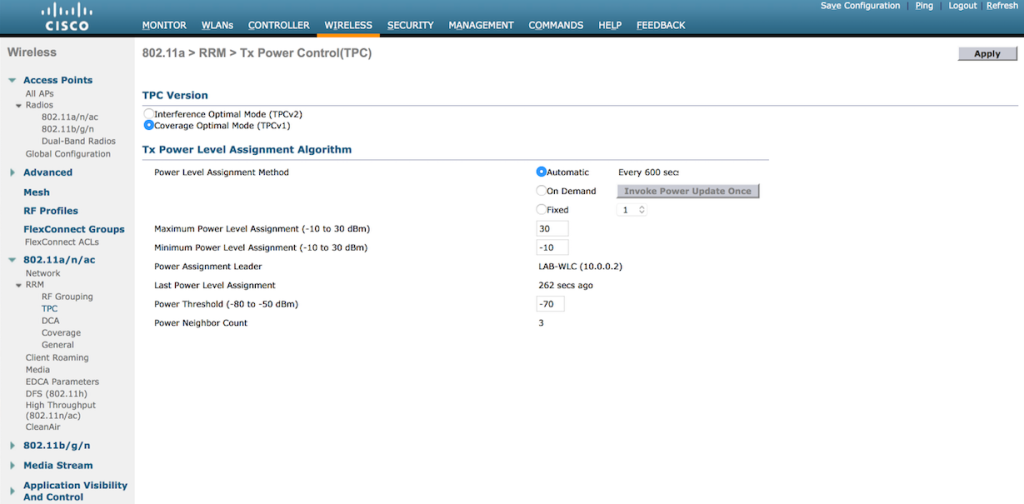
Here you can see the available settings for TPC in the WLC GUI. This particular controller is running 7.6 code, so your version may vary.
- You can either set TPC to run automatically, on demand, or at a fixed power rate on all APs. TPC is band specific, so if you want different settings for 2.4GHz and 5GHz respectively, you can have that.
- Maximum and minimum settings for transmit power are available. The defaults are 30dBm for maximum power and -10dBm for minimum power.
- The power threshold is the minimum level at which you need to hear the third AP for the TPC algorithm to run. The default is -70dBm. You can set it higher or lower depending on your needs. High density environments might require a level stronger than -70dBm, with -50dBm being the strongest level supported. If you don’t necessarily need to run things like voice, you might be able to get away with a weaker threshold, but you cannot go beyond -80dBm.
A Quick Sidebar on Maximum Transmit Power in 5GHz
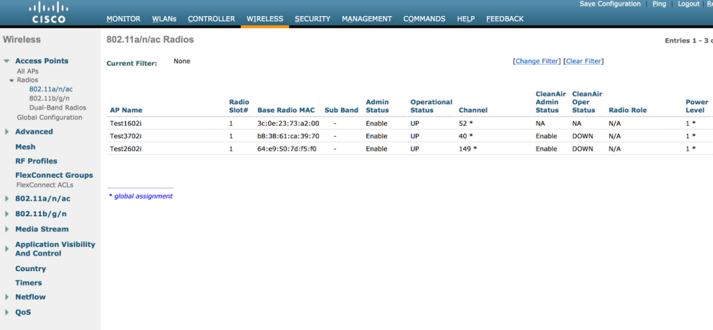
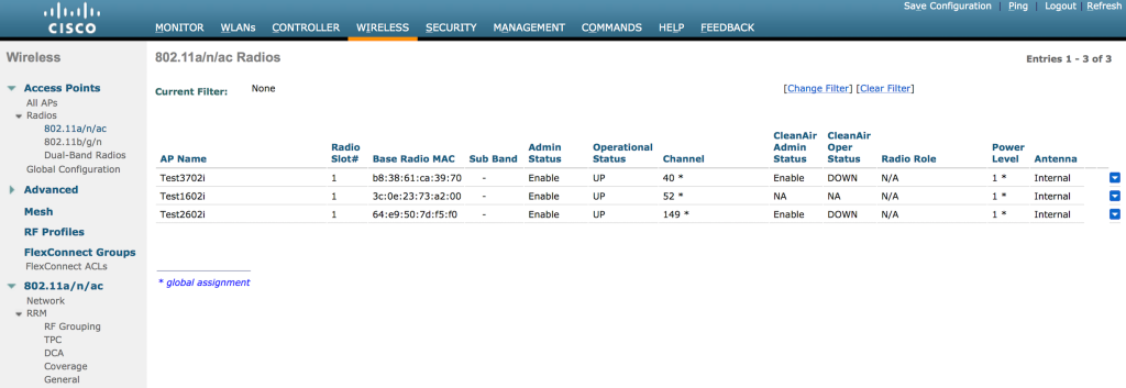
I set up the WLC with 3 APs active on 5GHz only. You can see that the power levels on the 3 APs are set to 1 in the image further down, which is maximum power according to Cisco. While it seems odd that max power would be a 1 and not some higher number, consider the fact that there are multiple maximum transmit power levels depending on which UNII band you are using in 5GHz. As a general reference, 20dBm would be 100mW and 14dBm would be 25mW. You could get 200mW(23dBm) of power using a UNII-3 channel vs UNII-1, which is maxed out 32mW(15dBm). That is a HUGE difference.
- UNII-1 power levels for channels 36-48:
- 1 – 15dBm
- 2 – 12dBm
- 3 – 9dBm
- 4 – 6dBm
- 5 – 3dBm
- UNII-2 power levels for channels 52-64(I didn’t test UNII-2 Extended, but I suspect it is the same:
- 1 – 17dBm
- 2 – 14dBm
- 3 – 11dBm
- 4 – 8dBm
- 5 – 5dBm
- 6 – 2dBm
- UNII-3 power levels for channels 149-161:
- 1 – 23dBm
- 2 – 20dBm
- 3 – 17dBm
- 4 – 14dBm
- 5 – 11dBm
- 6 – 8dBm
- 7 – 5dBm
To see the supported power levels in terms of dBm on 5GHz, you can run the following command on the CLI of the WLC:
show ap config 802.11a <ap name>
The output will look something like this after you go through a handful of screens showing other stuff:
***Update – Brian Long wrote a blog post on this very thing! You can read it here.
Back To The Testing…
You can see in the image below that with 3 APs active, they are all running at power level 1, which is the default when the radios come online.
So let’s see what happens when I add the fourth AP. If our understanding of TPC is correct, we should see the power levels come down since the APs are so close to each other and will have a signal strength of well above -70dBm between each other.
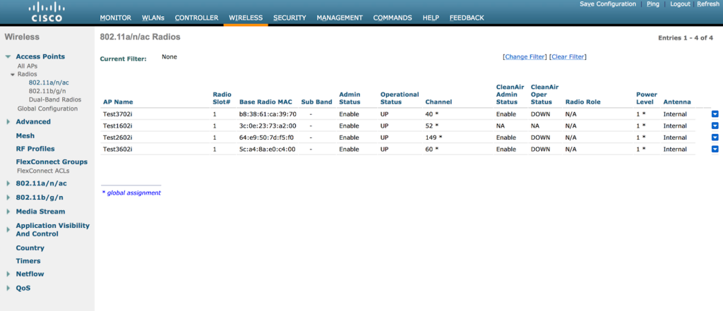 The fourth AP now shows up, but the power levels are still maxed out at 1. The AP’s are also using channels on all 3 UNII bands, so there is a huge disparity in output power right now. After a few minutes, the following shows up in the WLC:
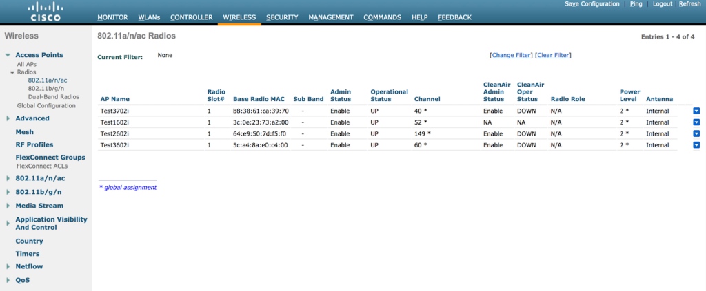 Now we can see TPC working. It has reduced all 4 APs to a power level of 2. Once the TPC algorithm kicks in, it will run every 10 minutes until it reaches a level where the fourth AP is just within the power threshold of -70dBm. Let’s see if it keeps reducing power.
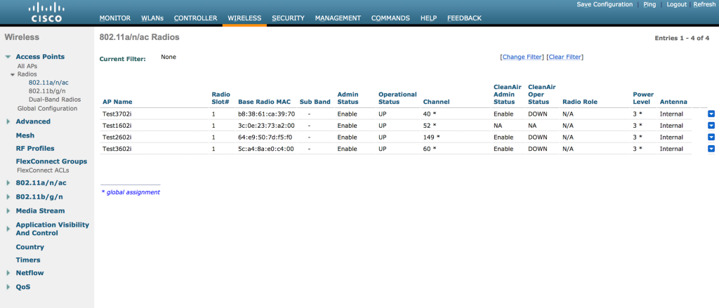 Now we are at a power level of 3. Ten more minutes pass and I see the following:
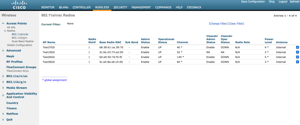 Two of the APs have been reduced to a power level of 4. Ten more minutes passed and power levels reduced even further. At that point, I powered off one of the APs to see if the power levels would go back to 1 since there was no longer a fourth AP. I didn’t get a screen shot in time to see all 4 APs at an even lower power level, but when I did grab a screen shot of the 3 remaining APs, one of them had been dropped to a power level of 5. I believe this happened prior to my unplugging the fourth AP.
Note – Power level decreases happen in single increments only, every time the TPC algorithm runs(every 10 minutes). To put it another way, it downgrades by 3dB max each cycle. Sam Clements pointed out to me via Twitter that when power levels increase, it can happen much more rapidly since the Coverage Hole Detection(CHD) and Correction algorithm is responsible for power increases.
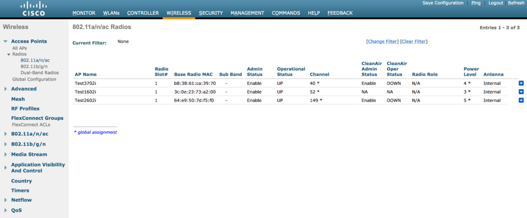 I waited for at least 30 minutes to see if the power levels would return to 1 for the remaining 3 APs, but they didn’t move at all. They stayed just like the above image.
If you want to see this work on the CLI in real time, you can issue the following command:
debug airewave-director power enable
After I had waited for over half an hour, I decided to power off one more AP. When I brought it back online, I saw all 3 of the APs slowly go back to a power level of 1. Here’s the first change I saw in the 3 remaining APs:
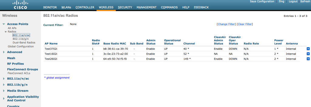 And then shortly afterward, I saw them back at max power.
It’s All In The Details
For wireless surveys, my company uses the Ekahau Site Survey product. It is a really neat survey tool and we use it for on site assessments as well as predictive surveys. When you define the requirements of the project, you can choose from a bunch of different vendor specific scenarios, or general wireless scenarios. I can apply those requirements to a predictive survey, or an on site survey where I am trying to determine if the existing coverage/capacity is good enough for the business needs.
Here’s a screen shot of the default requirements for the “Cisco Voice” scenario found in version 7.6.4 of Ekahau’s Site Survey program:
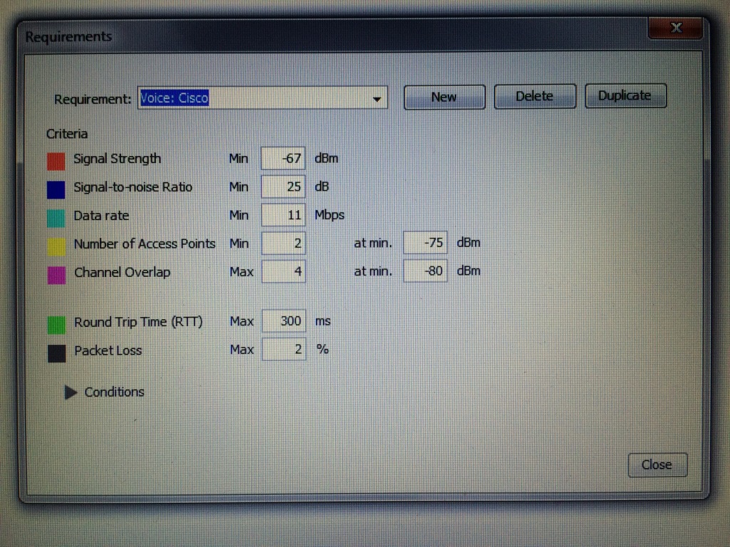 Pay careful attention to the “Number of Access Points” field. By default, it shows 2 APs with a minimum signal strength of -75dBm. If I am building a predictive survey for Cisco voice, I would need to have all of my coverage areas to see 2 APs at a signal of -75dBm or better. That’s perfectly fine, but I also have to consider the APs and how they determine, you guessed it, transmit power. If I change the value in the “Number of Access Points” field to 3 APs at -70dBm or better, I can build my predictive survey around inter-AP communication as well. In that scenario, I am not looking to cover the entire floor or building to that standard. I just need to make sure that all of my APs can see 3 or more APs at -70dBm or better. Of course, if I am not using Cisco wireless to support a Cisco voice implementation, I need to figure out how that other wireless vendor determines transmit power. Just something to consider when interpreting the results of an actual or predictive survey. It isn’t entirely about the clients and their relationship to the AP. AP to AP communication matters as well!
Closing Thoughts
Understanding how the TPC function works is pretty important when designing Cisco wireless networks. Failure to consider what all is involved in regards to transmit power on your APs could(not WILL, but COULD) lead to problems in the wireless network’s operation. However, if you want to manually set transmit power, that’s an option as well. Opinions differ on running RRM. I’m not sure there is a right or wrong answer. It depends. 🙂 I will say that I almost never see Cisco wireless implementations where RRM is not being used.
I don’t want to end this post without mentioning that some networks may be perfectly fine running APs at max power, especially on the 5GHz side. Your coverage may be enough to where there is minimal channel overlap(easily achievable in 5GHz with 20MHz channels and the use of all 3 UNII bands), and each AP can hear one or two neighboring APs at a decent level due to good cell overlap. You just might not have enough APs to trigger the TPC algorithm to run. That doesn’t mean “you are doing it wrong”. If it works for the business and all your users are fine, who am I to tell you that you need to “fix” it.
Hopefully this was beneficial to you if you needed a clearer understanding of how Cisco’s TPC function works. If you already have a good understanding of TPC and managed to read this far, feel free to shame humiliate correct me in the comments.


